The title of this article will probably have many people…

How Bent is Your Enlarger? by Andy Cross
When it comes to purchasing photographic equipment we always try to procure the best equipment we can afford. The best can mean different things to different people. It could mean the fastest lens available or the highest resolving power or the most durable.
If you are running a conventional darkroom the same applies to the equipment in there as well. We acquire the best enlarger and lens combination for our needs which is the hub of any analogue darkroom. But it all can be compromised if the enlarger is out of alignment.
Out of alignment in this case refers to the fact that all the enlargers I have tested so far , and the number is too many to recall, were out of alignment in that the negative carrier, lens plane and easel were not parallel to one another.
To ensure the image is printed as sharp as possible all three planes need to be parallel on both axis’s. The enlargers that seem to get out of alignment the most are those with moveable lens planes and tiltable heads. They often rely on index marks and center dents to keep them in alignment. Even tightening one of the locking knobs up more can put the planes out of alignment.
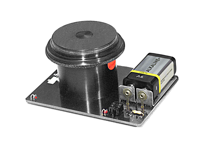
Although these types of enlargers are more easily put out of alignment the adjustments that cause it make it a lot easier to re-align them. Whereas enlarger’s that have fixed negative and lens planes are not as easy to correct. Checking the alignment has to be done with optical tools designed specifically for the job. There are a variety of them now but at the time I bought mine the only type readily available was the unit illustrated Fig #1A and Fig #1B which was made by Zig-a lign.


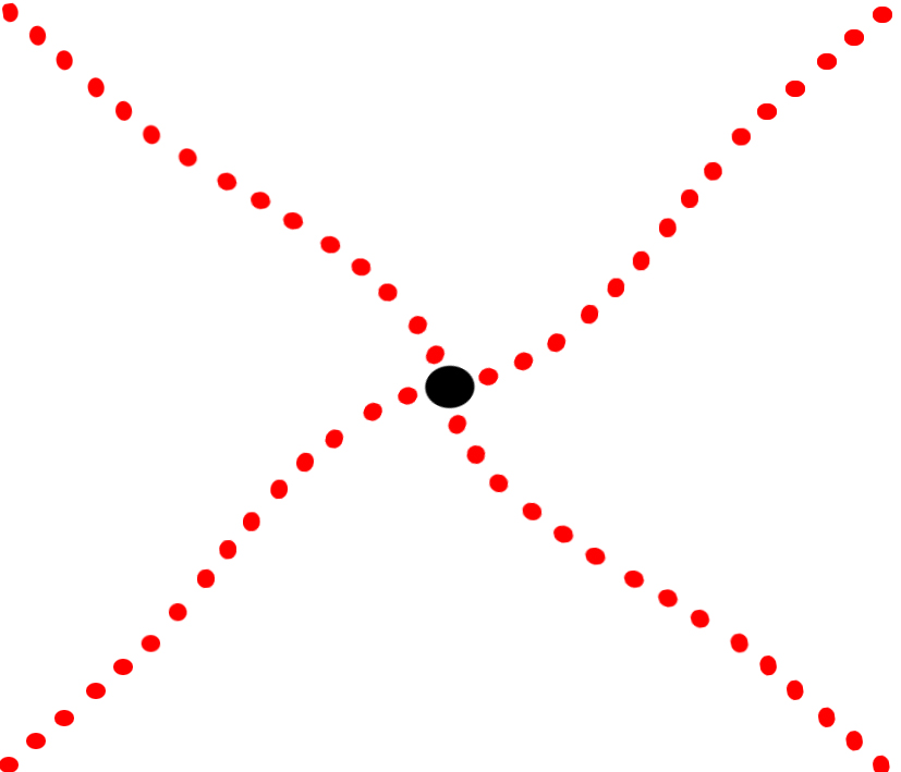
It consists of a prism attached to a front surface mirror with a viewing hole in the middle of it. It has 4 red LED’s attached to it, one mounted in each corner. The image of these LED’s being bounced back and forth between another front surface mirror, which is placed on another plane, need to be seen as a symmetrical cross. If they are not then tilts and swings have to be made to one or both planes to achieve alignment. In much the same way as tilts and swings are made on a view camera. The amounts though have to be much smaller.
There is very little to go wrong with the Zig – align system which are still available. If it does need repair most of the parts are available from many electronic component stores. I also used this system to align the mirrors in the Bermpohl one shot colour separation camera. See the article Back to the Future.
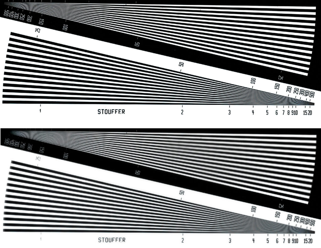
Unless one or more of the three planes, being the film plane, lens plane and easel, are out of alignment by a significant amount it may not be apparent that they need correcting. Apart from checking the alignment with an alignment tool the best way to check is with a resolution guide. See Fig #2. Run the enlarger to the top of the column and make the largest print possible. You need only expose two small sheets of paper. One from the middle of the projected image and another from the edge. Use the lens at full open aperture so the depth of field is the shallowest. Expose the target for the minimum time required to achieve maximum black.

Examine both prints. The edge definition should be virtually the same in both. By edge definition I mean the black edges should be as sharp and as well-defined from one another in both prints. If they are not then it could mean the lens has some aberrations in it you weren’t aware of or the three enlarger planes are not parallel with one another.
What you are really examining here is the high frequency information. Photographs may contain both high and low frequency information. I often use the scenario of a hot air balloon in a blue sky with smeary white clouds in it as an example of low frequency information. This sort of image doesn’t contain areas where the silver grains have to alternate from light to dark and back again many times over a short distance.
Whereas the case of a close up image of a back lit dandelion with tiny drops of water on each tine, the transition from light to dark happens multiple times over a very short distance. You may not notice any out of focus portions of the image containing the hot air balloon but out of focus areas will be quite apparent in the dandelion shot.
The re-alignment procedure I have adopted starts with checking all three planes. The negative plane is checked against the easel and then the lens plane checked against the easel. Most enlargers have fixed columns. If the adjustment needed, to get the negative plane parallel with the easel, is several millimeters then shimming the column where it attaches to the baseboard may be necessary. And before you ask yes I have seen them out as much as this.
You can use shim brass for this which comes in sheets in various thicknesses but these days I use mylar. Several sheets can be adhered to one another to build up the required thickness. If the head on your enlarger can be tilted for wall projection this is another option in correcting for the bulk of the movement required. However it only allows the tilt in one direction. On the opposite axis shims will still be required.
Do not try to fine tune with the column adjustments just accommodate the bulk of the movement required. The final adjustment can be made with shims under the easel. Another approach is to purchase eas- align. This device has micro adjustment screws under it making for very fine adjustment. I’ll look at this device in more detail a little later.
With the film plane and the easel now parallel with one another you can turn your attention to the lens plane. Again there are several ways to adjust the lens plane depending on the set up your enlarger has. Enlargers like the Durst, DeVere and other similar types may have moveable lens stages. They were made this way to allow tilting the lens plane when the scheimpflug effect had to be employed if correcting for converging verticals. Returning them to the neutral position simply relied on center dents or index marks and a tensioning screw.
In my opinion this was totally inadequate for the job. But the same locking mechanism that caused the lens to get out of alignment also allows it to be corrected more easily than those with fixed lens stages.
Again if your enlarger has lens stage movements it will only allow the corrections to be made on one axis. The opposite axis will still require shims for correction. This alignment is checked by attaching the alignment tool to the lens which in turn is attached to the lens board. After attaching the lens to the appropriate lens board, for the focal length of the lens , use one of the adapters supplied with the alignment tool, and attach it to the lens.
Ensure the lens board is attached in a manner that has the lens aperture numbers facing the front so they are easily read. Align the lens on the horizontal axis first using the moveable lens stage if your enlarger has this option. Then remove the lens board and place some shims the appropriate thickness where you think they need to go. This may take some time and several attempts to get right. Once this has been completed you are well on the way to achieving parallelism, if that’s a word, for your enlarger.
If you haven’t employed the use of an easel alignment stage like eas- align then it is best to transfer the shims used to a carrier plate. For this I use to use a piece of plate glass 6mm in thickness. The reason it is best to do this is because as you move the easel around the baseboard the mylar or Perspex shims will scuff the laminate finish of the baseboard. It will also peel away at the shims which after some time will need to be re-attached to the easel.
Transferring the shims to a glass plate not only alleviates this problem it can also act as a baseboard extension allowing you to position the easel over the edge of the baseboard if required. If you do this a small re-alignment of the easel may be required although the fine tuning if required is very minor.
A far easier method of keeping the easel parallel to the lens and film plane is to attach a set of micro adjusting screws to the base of the easel. See Fig#3 This essentially attaches a three legged stool to the base of the easel. Two of the legs are adjustable with fine screws while it pivots on the third. I have checked and they are still available from Zig-a-lign but any one with basic handyman skills could fashion one themselves.

Using such a device means the adjustment screws need to protrude from the front of the easel so you have access to them. This reduces the amount the easel can be pulled forward as the feet will drop over the edge of the baseboard. The use of the glass plate will also alleviate this issue as well.

Over time the alignment may need to be fine-tuned anyway because expansion and contraction of metal parts between summer and winter may alter things. Also the baseboard is usually made from thick laminated particle board. This may compress at the sight of where the bolts holding the column to it are attached. Industrial enlargers may use enameled cast iron or anodized aluminium which are very stable.
If you have made a print from something like a resolution guide before you aligned the three planes and another one after you might be surprised how much improvement there has been in edge to edge sharpness.

Irrespective of which alignment tool you use the procedure for aligning an enlarger is basically the same. The negative stage is brought into alignment with the easel plane first. Large adjustments should be done by shimming the column where it bolts to the enlarger baseboard. By large adjustments I am not talking in centimeters but millimeters. I have seen the column leaning as much as 3 to 4 millimeters. It’s best to use metal plates of varying thicknesses to achieve this. So when the bolts are tightened down again they are not compressing the wood over a small area like inserting washers do. The last few tenths of a millimeter can be taken care of with shims. After the enlargers stages have been made parallel with one another you shouldn’t need to do anything more other than check it once or twice a year.


So how bent is your enlarger ? You can’t tell just by looking at it. Only instrumentation will give you the answer. This isn’t something that many home darkroom users do or even many labs in Australia but in the USA and Europe it was carried out quite regularly. For what it costs to purchase an alignment tool verse the gains I would certainly recommend it.
Previous Post: Folio: A new series for View Camera Australia.


hello, very interesting article, the last thing I saw published is before 2001, I am interested in knowing how you made the socket to mount the ZD3,
I have an omega D5.
The idea is to align the three planes, if you can send me the information, it would be great.
1-Negative
2-Lens
3-Easel.
Greetings
Ricardo
Hi Ricardo,
I didn’t make any of the adaptors, reduction rings or anything else. They were all supplied by Bill Zigler. Bill passed away but I believe his son still has inventory. You might want to contact zig a lign. At zig zigaling.com
Regards,
Andy.